L2VPN Pseudowire Redundancy (MPLS AToM Redundancy)
The MPLS L2VPN is growing exponentially, back to the old days, customers were preferring FR and ATM VPN model due to the weakness of Peer-to-Peer VPN model at this time, but after MPLS become fact on the ground most of these customer migrated to MPLS L3VPN which solved all the Old Peer-To-Peer model issues, meanwhile the MPLS-L2VPN allows the service providers to provide different VPN models using the same network.
Like other network applications L2VPN redundancy is desired for services delivery continuity, The L2VPN Pseudowire Redundancy feature allows edge routers to detect a failure in the network and reroute the Layer 2 (L2) traffic to another endpoint, this feature provides the ability to recover from a failure in either the remote PE or the PE-CE link.
Before dissing the PW Redundancy features we need to highlight the potential points of failures in the L2VPN networks.
The Points of Failures including (but not limited to) hardware or software failure in CE, PE or P routers, Core uplinks failure, or attachment circuit failure.
Tow level of redundancy shall be used together to achieve optimum (not full) redundancy:
Level1:
Routing Redundancy
When connectivity between end-to-end PE routers fails, the network must be able to find an alternative path to the directed LDP session and the user data can take over.
Level2:
There are some parts of the network where this rerouting mechanism does not protect against interruptions in service, this parts include any failure that can not be recovered by routing protocols, for example hardware or software failures of the PW end points (Ingress/Egress PE), HW or SW failures on CE, PE-CE AC (attachment circuit)..etc, The L2VPN Pseudowire Redundancy feature enables you to set up backup pseudowires. You can configure the network with redundant pseudowires (PWs) and redundant network elements to achieve optimum redundancy.
Points need to consider:
While deploying this feature keep in mind that:
-L2VPN PW redundant feature not support for L2TPv3 (AToM with xconnect command Only)
-More than one backup pseudowire is not supported.
-Main and backup PW must support the same (Type of transport service, internetworking type)
-Main and backup PW can not be operational in the same time (The backup pseudowire becomes active only after the primary pseudowire fails)
Pseudowire Redundancy deployment:
When the primary pseudowire fails, the PE router can switch to the backup pseudowire. You can have the primary pseudowire resume operation after it comes back up automatically or manual using the xconnect backup force-switchover command.
Scenario1:
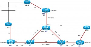
The Service Provider provide EoMPLS in point-to-point model to CUST-1, CUST-1 has tow sites connected as below:
Site A Connected to PE1
Site B Connected to PE2
Site A and B should never lose the connectivity in case of (PE2 HW/SW failure , CE-B HW/SW failure, attachment circuit failure between CE-B and PE2 ) so the ISP provide the customer with redundant link "AC" terminated on third PE "PE3" and terminated on different box from the customer side "CE-C", now the secondary or backup connection wont come up until the primary connection failed.
PE1#
interface FastEthernet0/0.10
encapsulation dot1Q 10
xconnect 160.1.255.1 3 encapsulation mpls
backup peer 160.1.255.3 4

PE2#
interface FastEthernet0/0.10
encapsulation dot1Q 10
xconnect 150.1.255.1 3 encapsulation mpls

PE3#
interface FastEthernet0/0.10
encapsulation dot1Q 10
xconnect 150.1.255.1 4 encapsulation mpls

PE1#show mpls l2transport vc
Local intf     Local circuit              Dest address    VC ID      Status
-------------  -------------------------- --------------- ---------- ----------
Fa0/0.10       Eth VLAN 10                160.1.255.1     3          UP
Fa0/0.10       Eth VLAN 10                160.1.255.3     4          DOWN

PE1#show xconnect interface f0/0.10
Legend: XC ST=Xconnect State, S1=Segment1 State, S2=Segment2 State
UP=Up, DN=Down, AD=Admin Down, IA=Inactive, NH=No Hardware
XC ST  Segment 1                         S1 Segment 2                         S2
------+---------------------------------+--+---------------------------------+--
UP pri ac   Fa0/0.10:10(Eth VLAN)        UP mpls 160.1.255.1:3                UP
IA sec ac   Fa0/0.10:10(Eth VLAN)        UP mpls 160.1.255.3:4                DN
let's get down the AC between PE2 and CE-B to check the backup connection
PE2#conf t
Enter configuration commands, one per line.  End with CNTL/Z.
PE2(config)#int f0/0.10
PE2(config-subif)#shutdown

PE1#show xconnect interface f0/0.10
Legend: XC ST=Xconnect State, S1=Segment1 State, S2=Segment2 State
UP=Up, DN=Down, AD=Admin Down, IA=Inactive, NH=No Hardware
XC ST  Segment 1                         S1 Segment 2                         S2
------+---------------------------------+--+---------------------------------+--
IA pri ac   Fa0/0.10:10(Eth VLAN)        UP mpls 160.1.255.1:3                DN
UP sec ac   Fa0/0.10:10(Eth VLAN)        UP mpls 160.1.255.3:4                UP
Also we can switch over the to the backup connection manually as below:
PE1#xconnect backup force-switchover peer 160.1.255.3 4

PE1-A#show xconnect interface f0/0.10  detail
Legend: XC ST=Xconnect State, S1=Segment1 State, S2=Segment2 State
UP=Up, DN=Down, AD=Admin Down, IA=Inactive, NH=No Hardware
XC ST  Segment 1                         S1 Segment 2                         S2
------+---------------------------------+--+---------------------------------+--
IA pri ac   Fa0/0.10:10(Eth VLAN)        UP mpls 160.1.255.1:3                DN
Interworking: none                   Local VC label unassigned
Remote VC label 16
pw-class:
UP sec ac   Fa0/0.10:10(Eth VLAN)        UP mpls 160.1.255.3:4                UP
Interworking: none                   Local VC label 22
Remote VC label 23
pw-class:
Best Regards,
Mounir Mohamed, CCIE#19573


